
So in the previous parts which you can find here and here between my son and I – we’d managed to get power back to the kitchen, install the base units and fit the counter tops.
In between part 2 and this one I gave the walls a mist coat of watered down Dulux Supermatt and then painted properly. I have not included that as a detailed description of painting would make my writing even more boring than it already is!
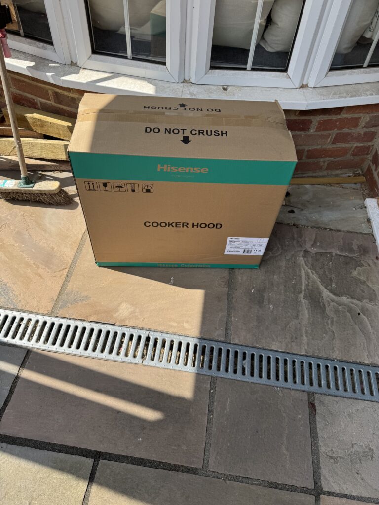
Therefore it was now onto the installation of the new extractor unit that I had bought. This needed to go in before fitting the cupboards and Splash-Back (which I had not had made at this point – more on this later). My reasoning for this was my plan would be to fit everything around the cooker and extractor. It would be easier to re-plan cupboards and splash-backs but less so in the case of fixed electrical installations if something was wrong.
- Install a new extractor fan for the hob
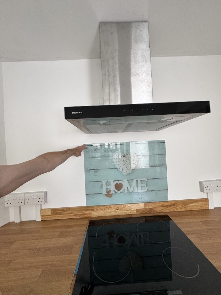
This was going to be an Interesting job (do you notice that I tend to use the word “Interesting” instead of a “right ball ache“). The extractor was an awkward shape and with an uneven distribution of weight and it had to be installed at a very exacting height above the hob and distance from the ceiling as well as being perfectly level to comply with UK regulations.
In the UK extractor units should be 650mm above the hob if it is electric (this includes Induction) or 750mm if the hob is gas. In my case, my hob is Induction so it had to be mounted at 650mm, but I added a couple of millimeters just to be on the safe side.
There are also a whole load of rules and calculations if you have decided to vent your extractor related to its ducting run, however I decided that I was going to use my extractor in re-circulation mode as I didn’t fancy installing ducting out through my new(ish) kitchen roof.
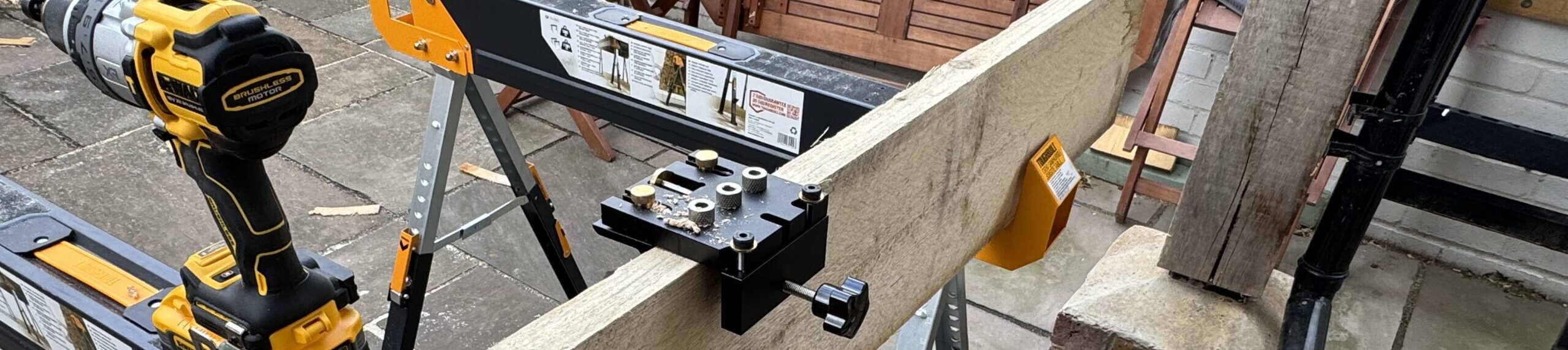
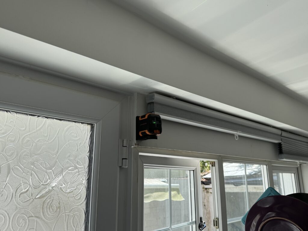
I started off by getting the markings for the unit on the wall. This was accomplished by mounting my laser level at the correct height on the opposite wall and then marking it out in pencil.
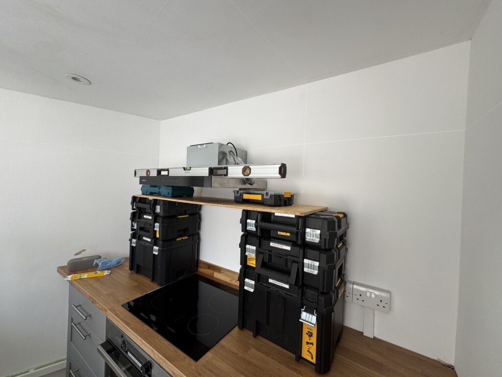
This part was the ball ache bit. I was never going to get the extractor on the wall to mark out the drill holes on my own and I had no specific tools or “lifts” that could support the weight of it whilst I marked everything up.
So I had a ponder for a bit and finally came up with the idea that I could use a mix of my DeWalt T-STAK cases and an off-cut of the OSB board that I had left over from leveling up the floor to sit the unit on top of and through a “mix and match” of the two I *should* be able to get it level to the correct height that I had already marked out on the wall.
In the end the solution was a mix of the T-STAK cases, OSB, a Makitia Case, a Stanley Screw case and one book which got me to the correct height and everything being level. I was able to then mark where the Rawl Plugs and Screws needed to go and then mount the fan.
Just on the point of Rawl Plugs and Screws – manufacturers tend to supply their wall mounted appliances with the cheapest possible option in terms of fixings. My advice is go out and invest in high quality screws and Rawl Plugs and use them instead to mount the product.
The supplied fixings with my extractor were general purpose at 40mm in length and I took them to 60mm and it is rock solid on the wall.
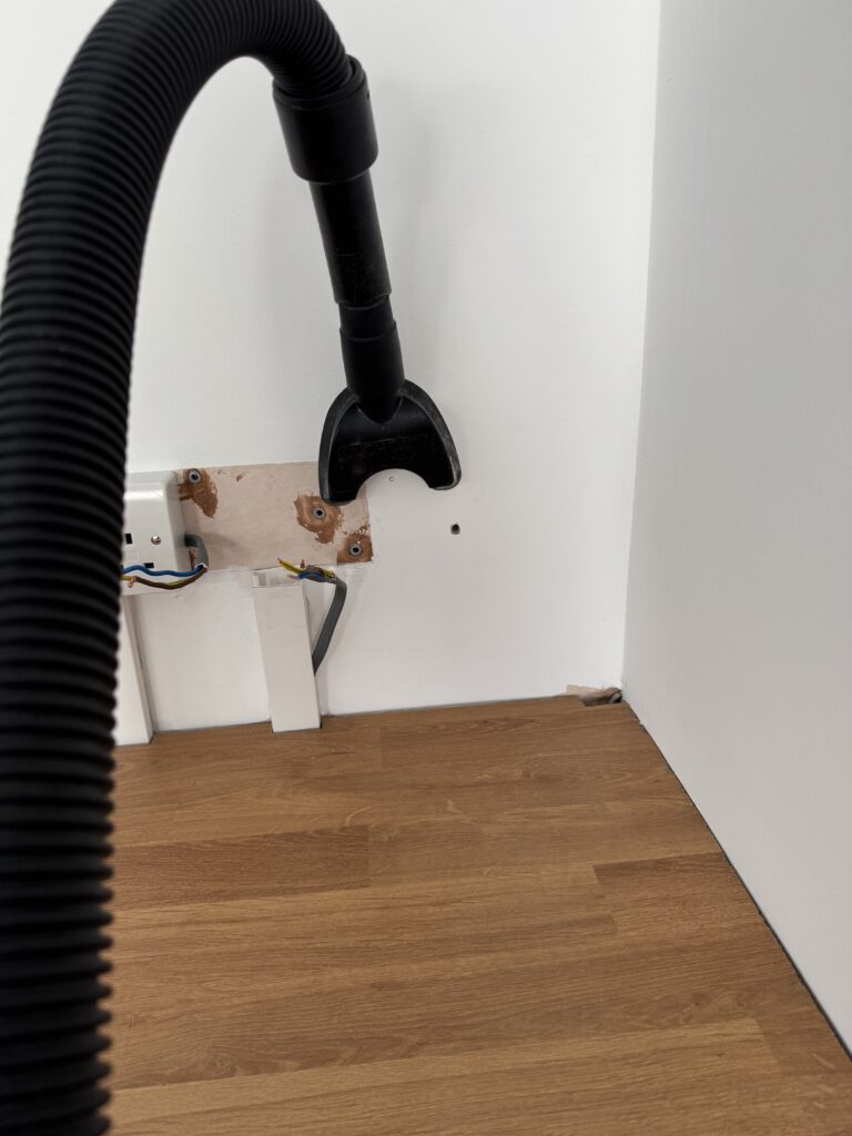
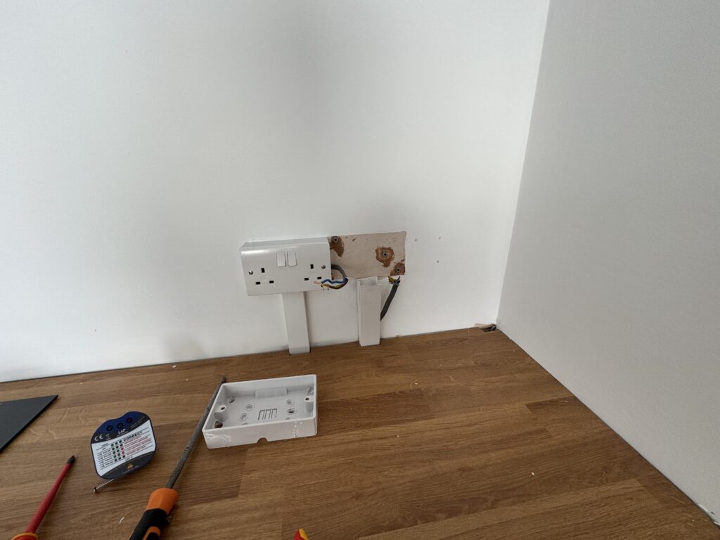
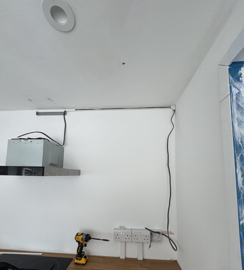
With the extractor now fixed into place and level it was time to run the electrical feed. In hindsight, with a bit of better planning I could have run this when my lad was doing the socket ring.
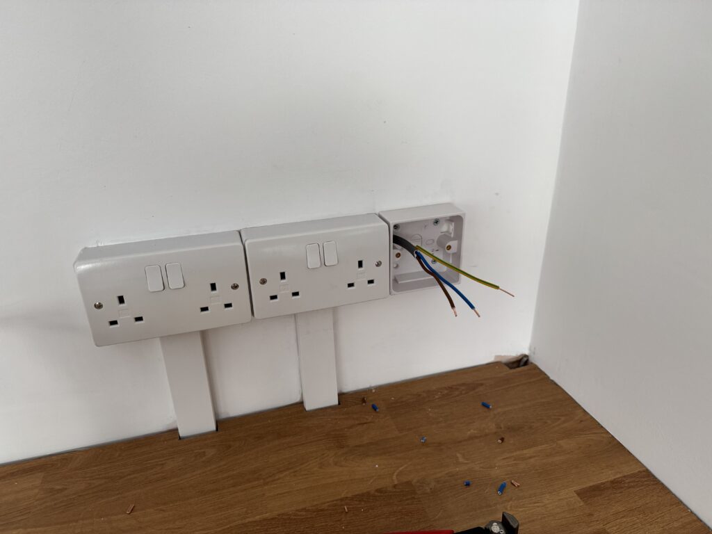
This would have given me a chance to get it a little more aesthetically pleasing – but I was where I was – so my idea was to run a fused spur off the first socket in the kitchen.
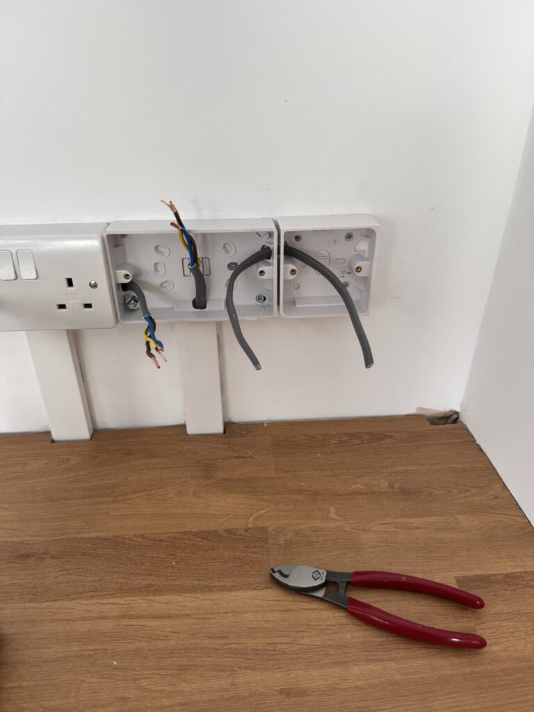
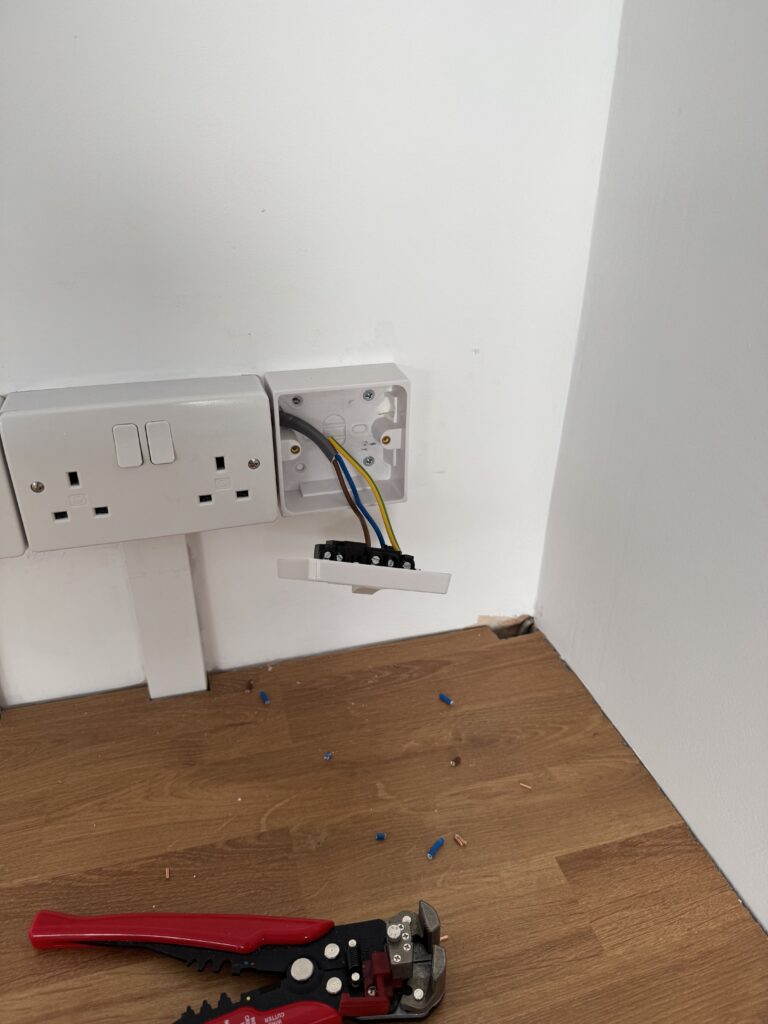
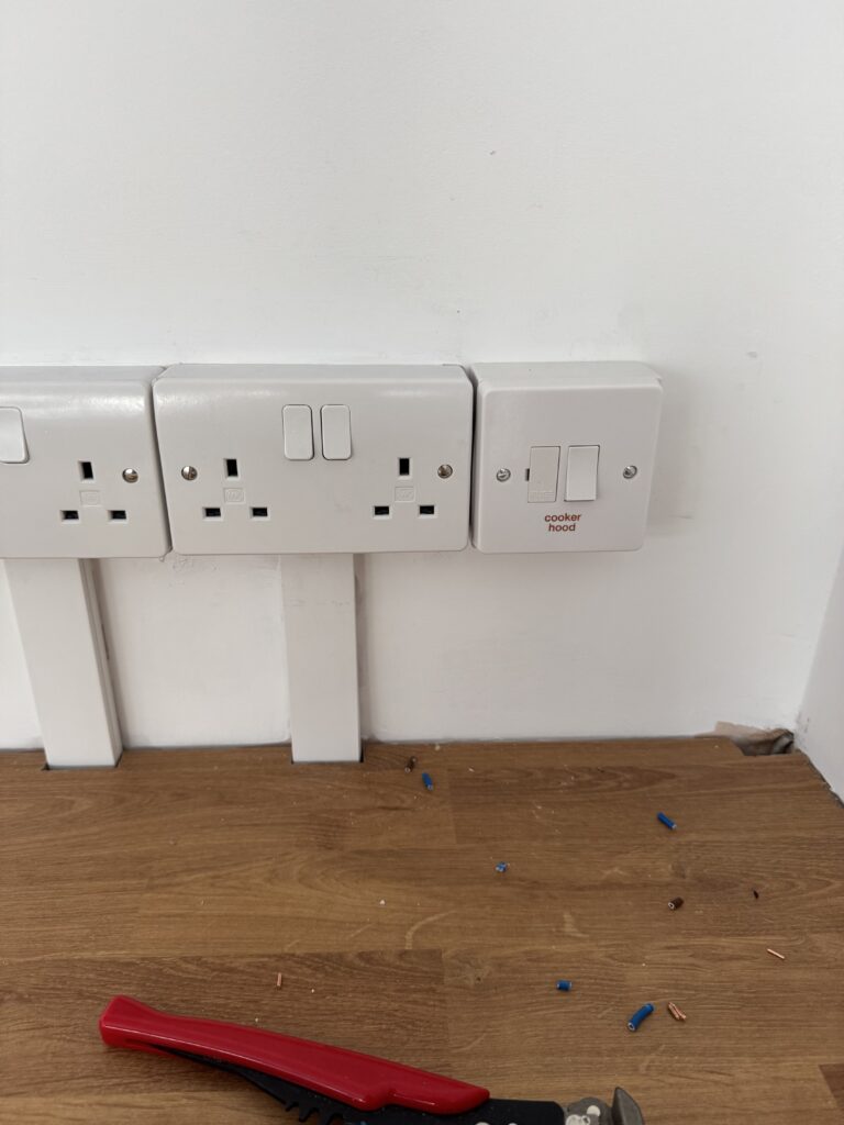
So, I put a single back box onto the wall right next to the socket, ran a loop wire in between the socket box and single back box connected the loop wire into the terminals on the socket plate and then connected up the extractor FCU (which I fused at 3amps).
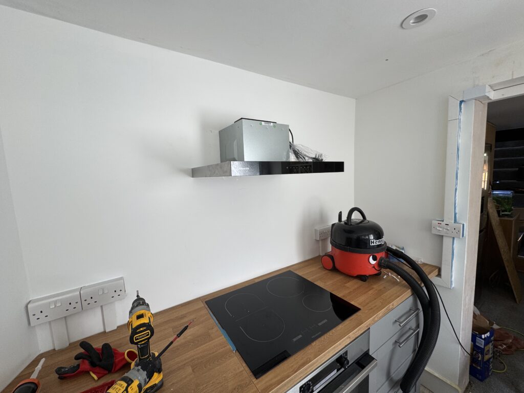
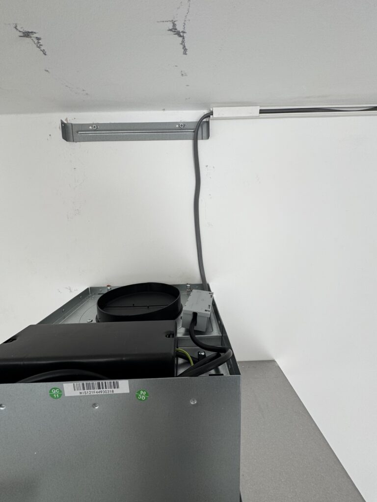
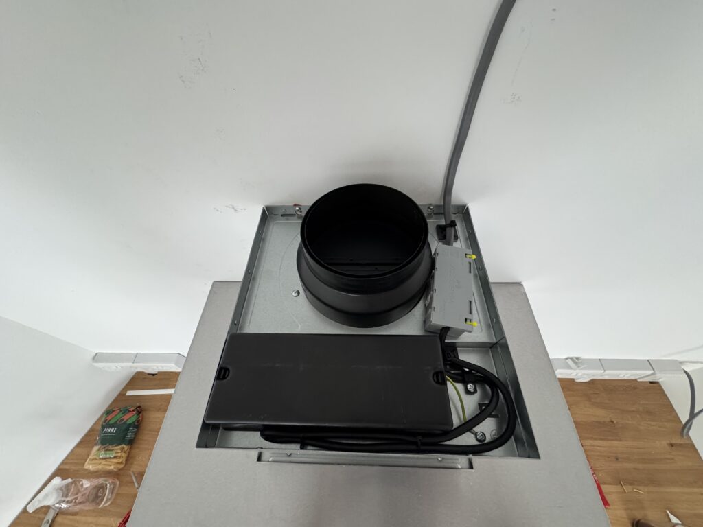
I then installed the extractor chimney bracket on the wall (this holds the adjustable chimney in place when fully assembled).
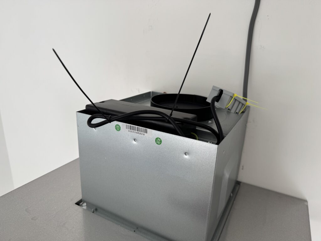
Then from the FCU I then ran a length of 2.5mm T & E up the wall and along the ceiling in trunking to the extractor unit where I terminated it into a WagoBox which would be secured inside the extractor chimney housing.
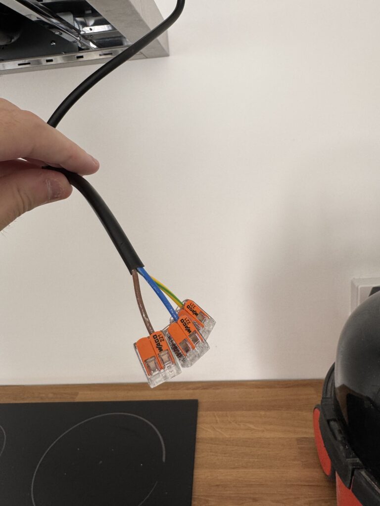
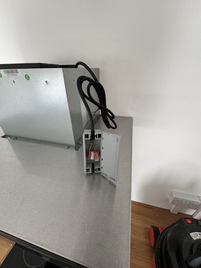
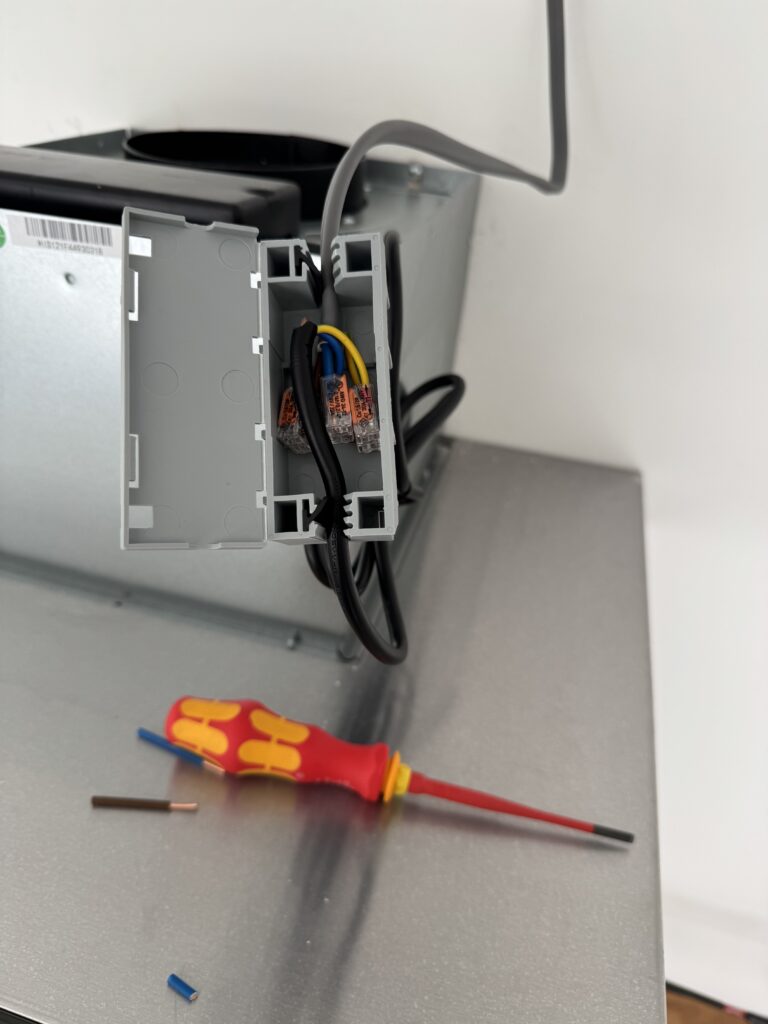
The extractor came supplied with a line cable with a 13amp plug attached, however the instructions also detailed how you could adapt the cable into a permanent supply – basically cut the plug off and terminate it into a FCU rated at 3amps – which was basically my plan in the first place!
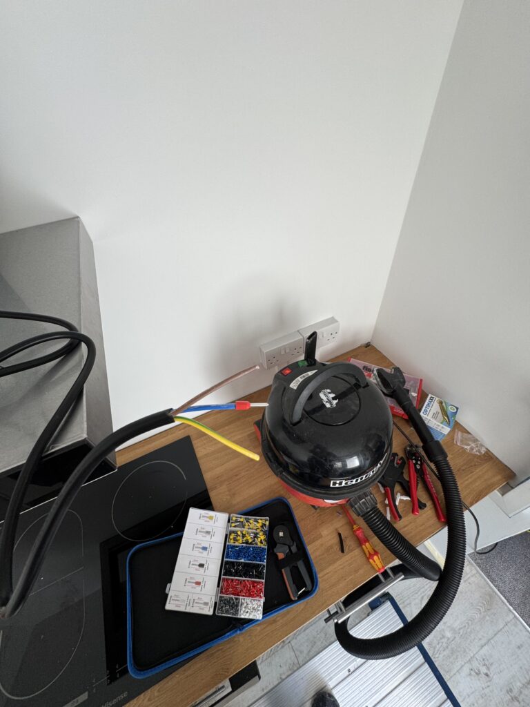
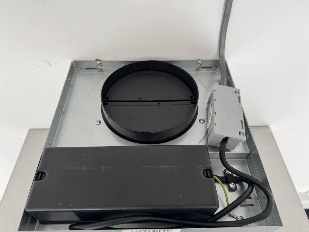
I cut the plug off, stripped the cable back, ferruled the stranded ends and put them into the corresponding live, neutral and earth Wago connectors which were inside the WagoBox I then secured the WagoBox down into the top of the unit using stuck down cable ties so the box wouldn’t be rattling around during operation.
It is admittedly puzzling that the fan came with a molded 13amp plug on the line cable, but if you directly wire it into the mains via a FCU you should take the fuse down to 3amps as part of a permanent feed because the physical switch on the FCU becomes the isolator.
To all intents and purposes the FCU becomes the plug so it being 13amps shouldn’t make a difference.
I guess it is probably something to do with a socket being a receptacle that you can physically remove the connection to the mains in an emergency, but, to my mind that isn’t solved totally by fusing the unit down to 3amps.
However, I followed the instructions I was given as the max draw of the extractor would never get near 3amps – so you could argue that having a factory 13amp plug is the incorrect configuration by default in the first place!
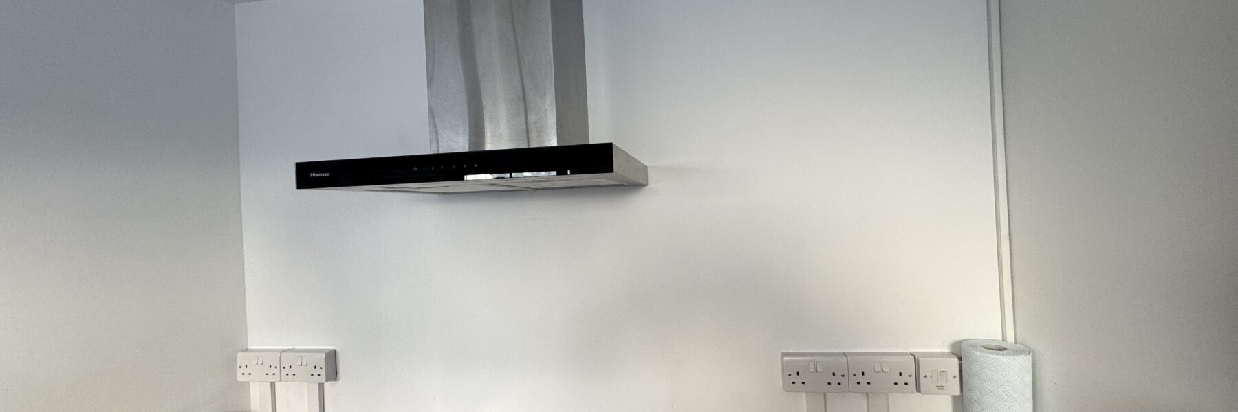
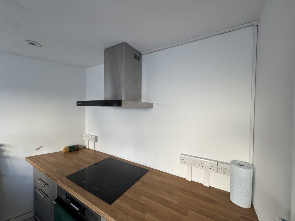
It was now time to mount the chimney to the top of the extractor onto the bracket – and whilst I was pleased that the measurements that I had taken for the trunking to align perfectly along side it with enough space for the cable to pass through without any pressure being applied to the T & E – it was a bastard to fit!
Anyhow after a lot of swearing and trying not to sever cables I got it on. I restored power to the kitchen and tested and everything worked perfectly!
Now that the extractor was in – I needed a lay down for a bit before I moved on to:
- Re-Install the cupboards
- Make and fit a number custom shelving units
- Sand and re-seal the existing sink counter top
- Cut, sand and fit counter up-stands & Fit a new Splash back for the hob
To be continued in part 4!