
In part 1 I set the scene for what, to date has been my biggest project – my kitchen refit!
Within part one I set out the list of tasks (or the plan) that I needed to work through (I called it the sequencing) – in this part I am going to put a little more detail around some of the more interesting parts in the build and how they went.
As a reminder the plan was:
- Re-install the new oven and hob feed
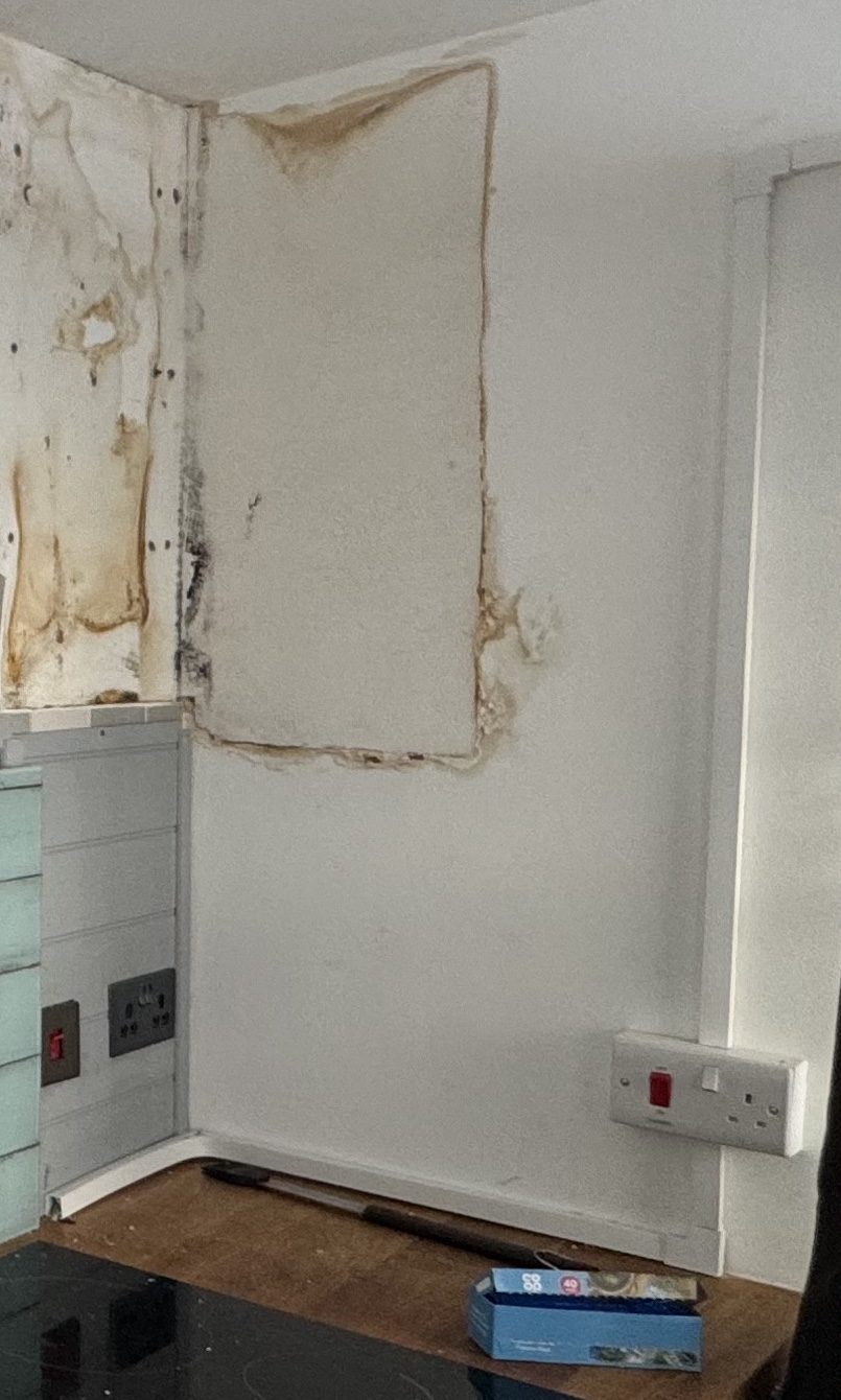
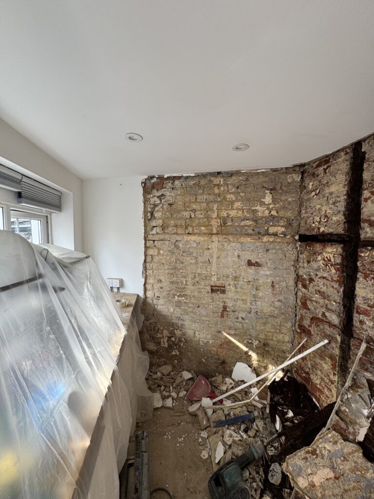
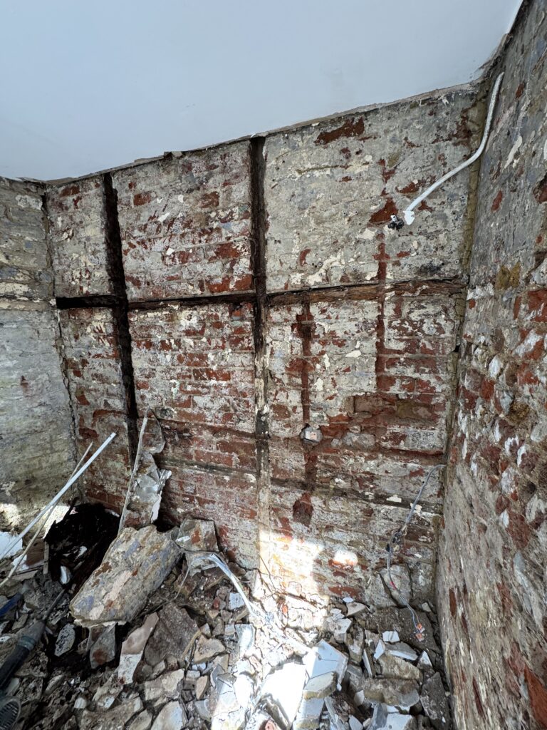
So as mentioned in part 1 – the refit of the kitchen was pretty much starting from scratch.
In preparation for the plaster work I had decided to strip out all of the electrical wiring and endpoints in the walls. They were saturated with water so I had decided that after the tanking had been completed all of the electrical installation would be surface mounted.
First up from an electrical standpoint was the oven and hob feed as we’d been without the ability to cook in a meaningful way for about 4 months by this point.
I had a new source feed from the CCU which was installed by a “qualified” electrician. Basically the old feed had been compromised by damp ingress from the walls – so, I had a local sparky come in and run a fresh surface mounted leg from the board.
If you have ever heard of the term “wood butcher” in the context of carpentry – this chap was the electrical equivalent! He was a lazy fucker who whilst running a fresh 6mm T &E cable to the kitchen decided to:
-
- Drill a hole in the side of my CCU for the cable and not fit a gland.
- Do the worst trunking job throughout the living space – using a SDS drill in hammer mode to make the trunking holes in plaster board and therefore cracking the hell out of it.
- Ensure that the need for a spirit level for the trunking was surplus to requirements – he just eyeballed the whole thing. Trouble was that clearly one of his eyeballs was set 20mm lower than the other.
- When he finally arrived with the feed in the kitchen and you might think that he might have run out of ideas on how to fuck up trunking even more – he came up with another one!
-
- Use a cooker feed that has clearly been in the Vauxhall Astra for about 20 years as the “Power On” indicator didn’t work.
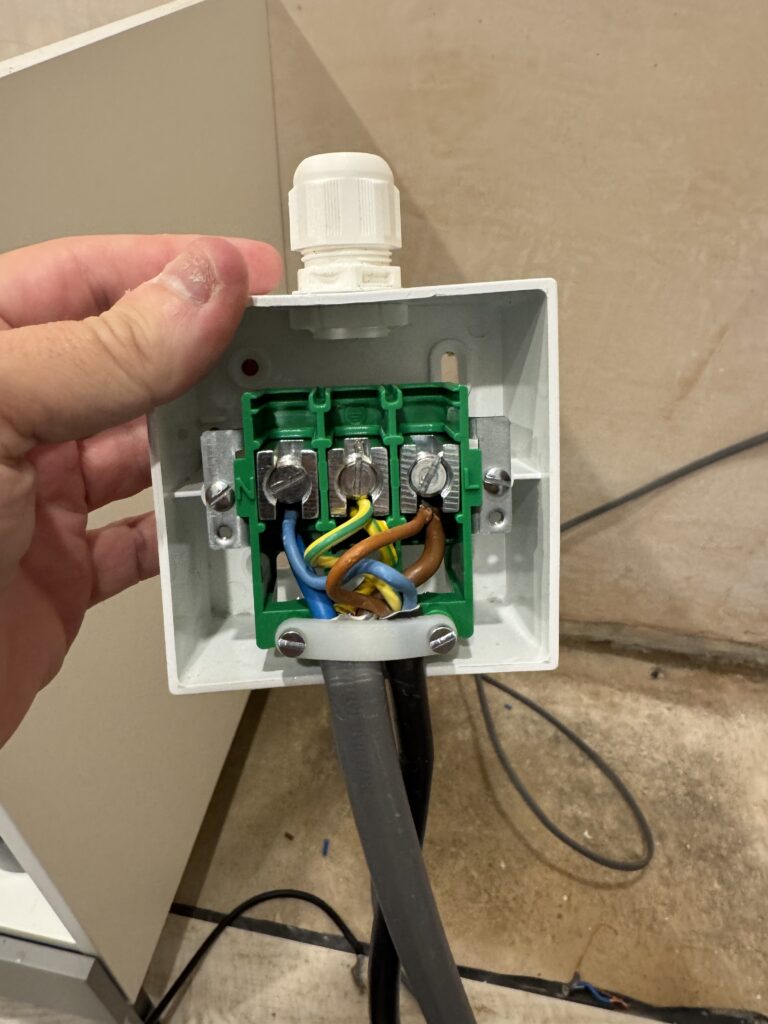
- Install a junction box for the hob and cooker which was rated at 25amps (I covered my issues with this in part 1).
- Managed to leave bits of MY CCU “spare” e.g. stuff that was clearly inside it – but – were left over after he has taken the cover off and drilled a hole into it.I still don’t know what those bits were part of as clearly I won’t take the cover off to have a look.
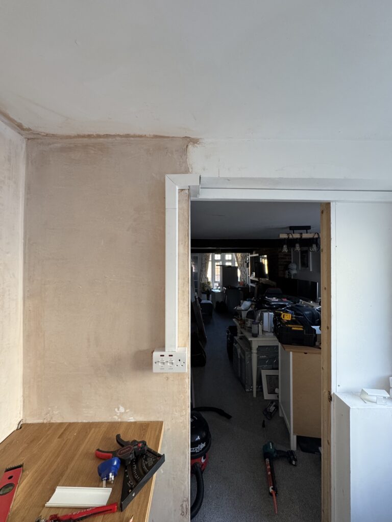
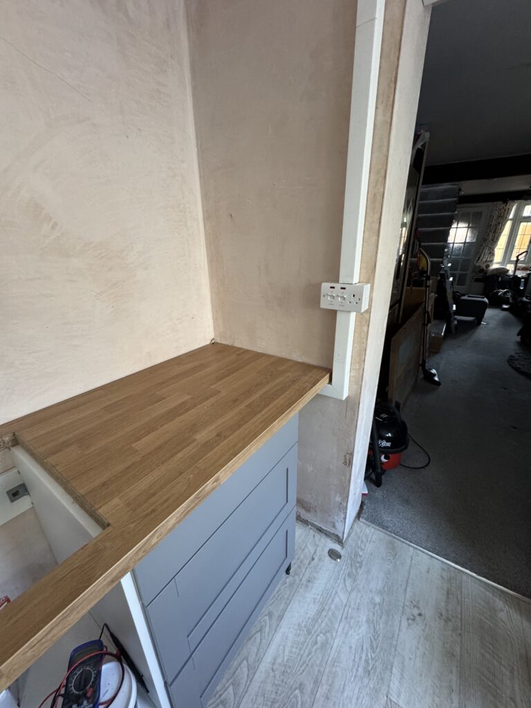
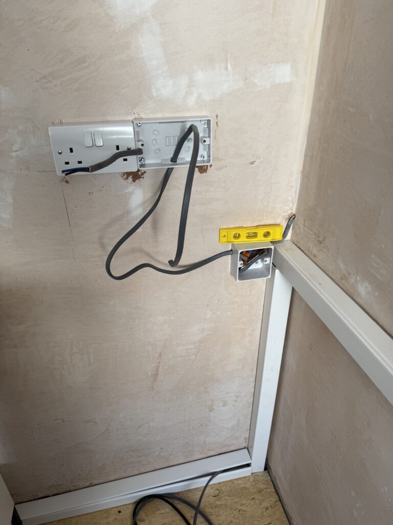
In the UK a cooker switch (or isolator) should be positioned a minimum of 100mm away from the edge of the hob, not be above the cooker or within a distance where it can sustain steam or heat damage and must be visible / accessible within 2 meters of the cooking appliances. You will see from the photos in the gallery that I had made sure that my chosen location for the feed met all of these conditions:
Now with the feed in place it was time to get the hob and oven installed (and finally be able to eat home cooked meals for the first time in months).
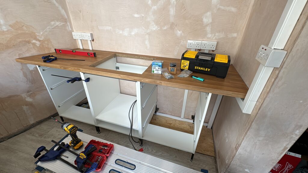
Cutting the counter top and the hole for the hob was an “experience“. I had never done counter work before (although, I had watched loads of videos on how to do it online – so had a rough idea) – but what made it more interesting was the angle of the rear kitchen wall.
In the photos below, you will see that it has an interesting angle which was around 28 degrees (from memory) so I had to get that cut first.
This involved measuring from the right hand wall (where the cooker feed runs from) to the furthest point on the back wall at the width of the counter – then from that point cutting the angle.
So, for example;
If the counter is 1.8 meters long, with a width of 70 cm and from wall to wall the measurement is 1.6 meters you would cut the counter to 1.6 meters and then at the left most point (which goes against the back wall) strike a line from the front to the back at 28 degrees and then cut along that.
I used a jig saw at the time to make that cut as I didn’t have a table saw. I did this with the help of a bit of timber that I put alongside the line to use as a fence to make sure that the cut was straight. After which I took the material into the kitchen to ensure that the counter fitted and it did – I was a few millimeters out on the angle but I wasn’t that worried as I knew that I was going to install up-stands on the counter that would hide the slight gap.
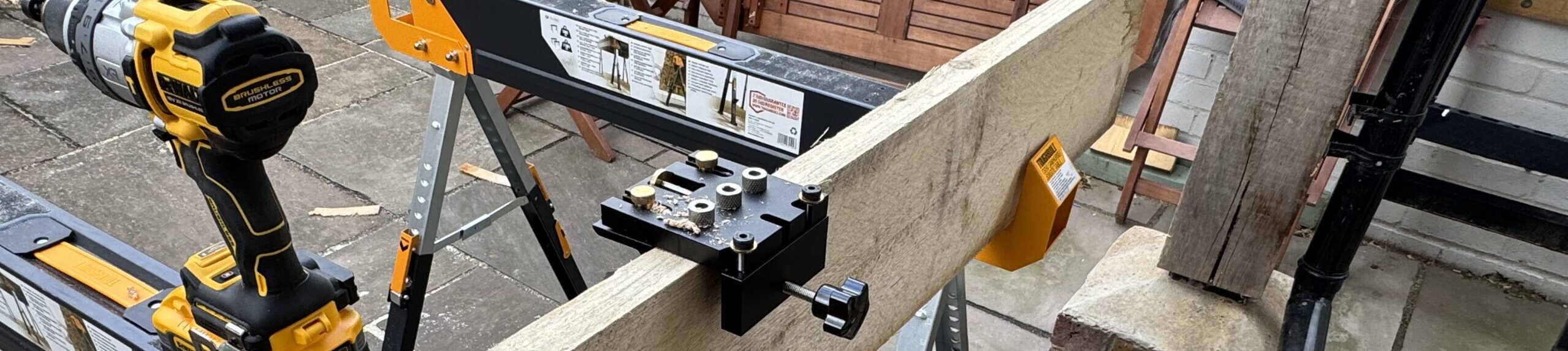
Next up was cutting the hole for the hob. I had seen this done a few times online and I was pretty confident that I could make it.
The first thing that I did was make sure that where I was going to fit the hob lined up with the oven in the floor unit below and marked that out on the counter. I then had to make sure that this then aligned with where I intended to install a Splash back on the wall and marked this out too.
With this all marked up it was time to take the counter outside and cut the hob recess. Inside the marks that I had made to align with the oven and splash back I drew out the measurements for the hob (these were in the manufacturers manual) on the counter.
I was going to again cut this with my jig saw, but first I drilled four holes inside the markings that I had for the hob, then put a bit of timber along each line to use as a fence to ensure each cut was straight. It is a good idea to also secure a batten across the area (only screwing this into the part of the counter which is going to be waste but overlapping the cut lines) as this will stop the jig from biting when the material drops and you can then just lift it out.
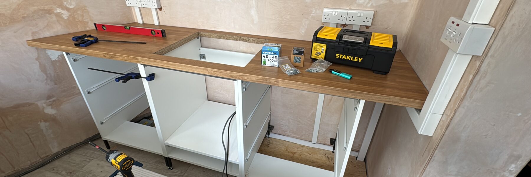
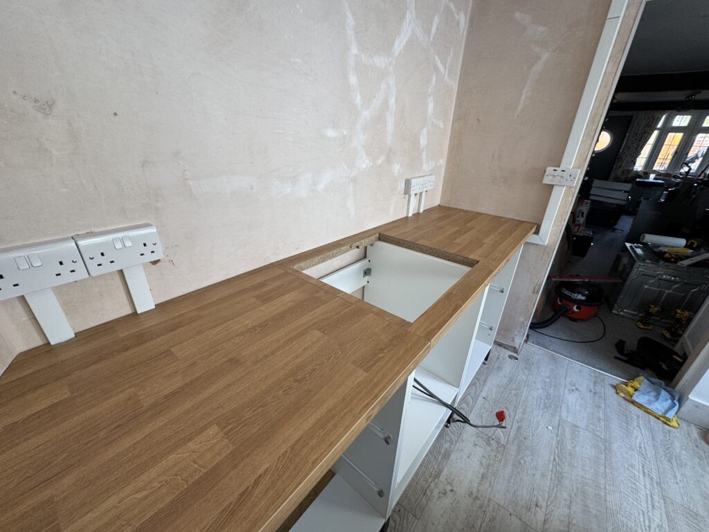
The photos below are taken from a little further on in the process as you will be able to see that there are sockets present – and clearly I had also cut the counter top both into place and the hole for the hob. I didn’t get any photos of the oven and hob installation and wiring as, to be frank that was fiddly.
- Re-install the kitchen socket ring
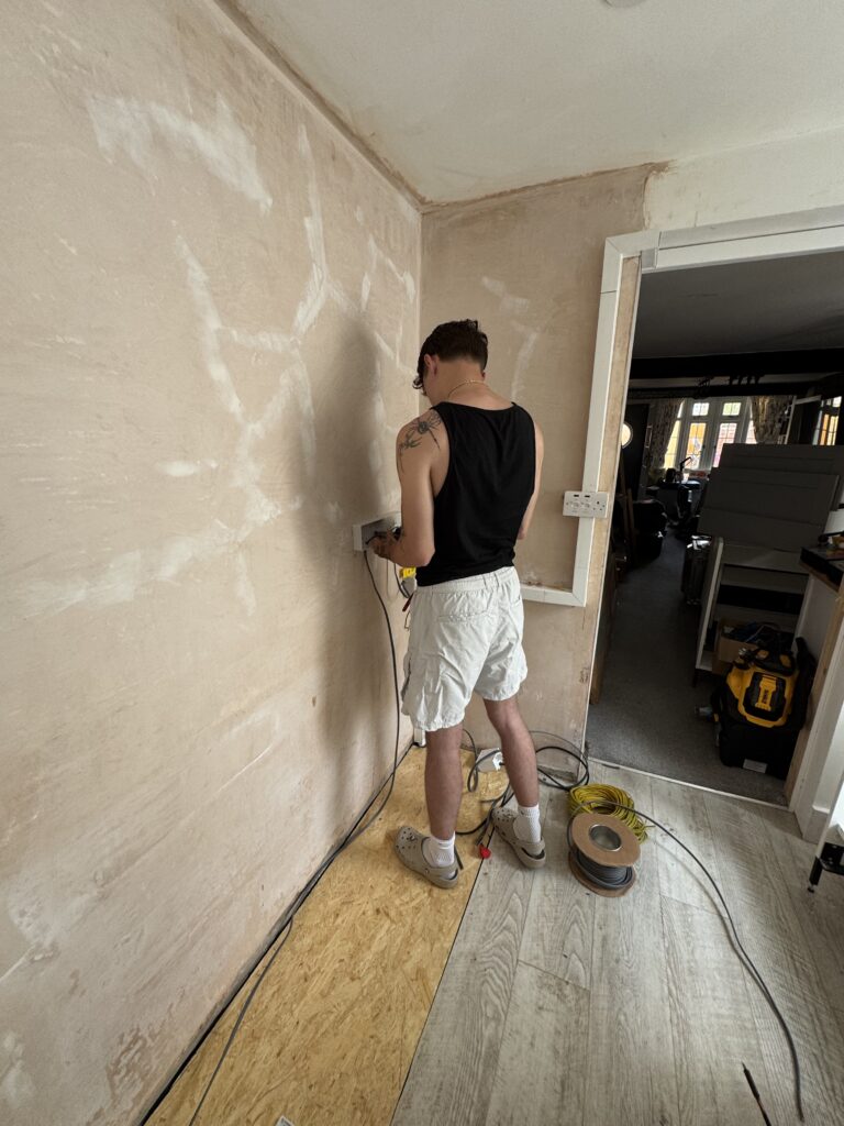
The socket ring was the next step in the re-fit. This was both “interesting” and a joy as it was something that my lad and I worked on together. He’s now a qualified sparky so he did a lot of the work.
What was nice, aside from working with him on the project – was he was able to verify that my design for the ring final was both safe and not bonkers!
The old kitchen had a grand total of two double sockets (one set above counter and one set below counter), a single spur off the ring for the old extractor and then some work of the devil socket behind a built in fridge which went to a FCU (fused connect unit) that was wired incorrectly so the FCU (fused connection unit) didn’t actually isolate anything – it was really more of a junction box and dangerous as fuck!
So, I stripped it all out (as mentioned) and only left the ring final feed from the CCU.
Before the electrical work could begin I needed to level out the floor where the old floor units had been.
Essentially the previous owner of the Shire had installed laminate flooring but had put it in AROUND the existing units – resulting in part of the floor where the units sit being around 11mm lower than the laminate.
This would be a pain for the new units as the leg adjustment didn’t stretch that far and I wanted to be able to a moisture barrier between the concrete floor and the electrics that I wanted to floor mount.
To do this I got hold of a large sheet of 11mm OSB board and some waterproof membrane, I cut both to the size of the gap (the membrane a little longer to allow for some overlap) and then fitted into place.
I wasn’t worried about looks here as the board and membrane would be covered by the units.
” You might be thinking – why put down membrane – if you had a further damp issue should you not have fixed it?
Well, the membrane was down to protect against ground water rather than damp. The Shire’s foundations are clay – I don’t have a huge problem with it, but points during the year there is a risk of it rising and making the concrete which makes up the floor damp.
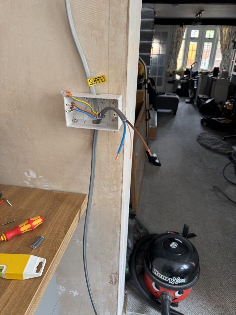
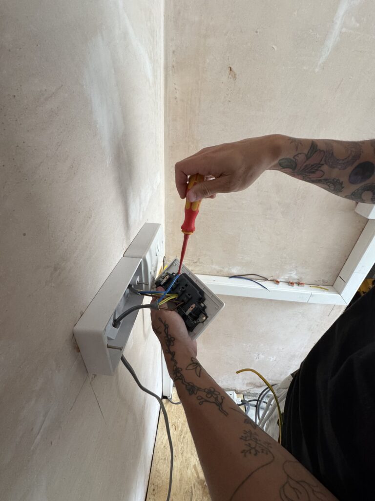
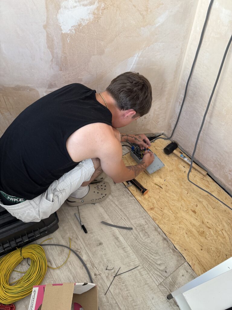
Now with all that prep done we started the electrical work off by lengthening the wire that ran from the CCU as there was very little slack left on it after all the plastering work. This was accomplished by fitting a junction box to the wall at the point of entry and then extending the length up from the junction to the first double socket.
One of the challenges which needed to be overcome at this stage was fitting the electrical fixtures on the walls. Tanking systems create a waterproof barrier between the moisture and the surface skim finish.
If you drill into them you risk creating a bridge between the barrier and top layer and your damp problems return.
The solution to this was to drill the holes for the fixings, vacuum them out and then fill them with a waterproof silicone sealant. After you have done that you can insert the Rawl plugs which completes the water proof barrier.
The good thing about this approach is that it is supported by the company who did the work so no guarantee issues to be worried about, the bad thing about this approach is that it is messy and you end up with sealant everywhere no matter how hard you try no to!
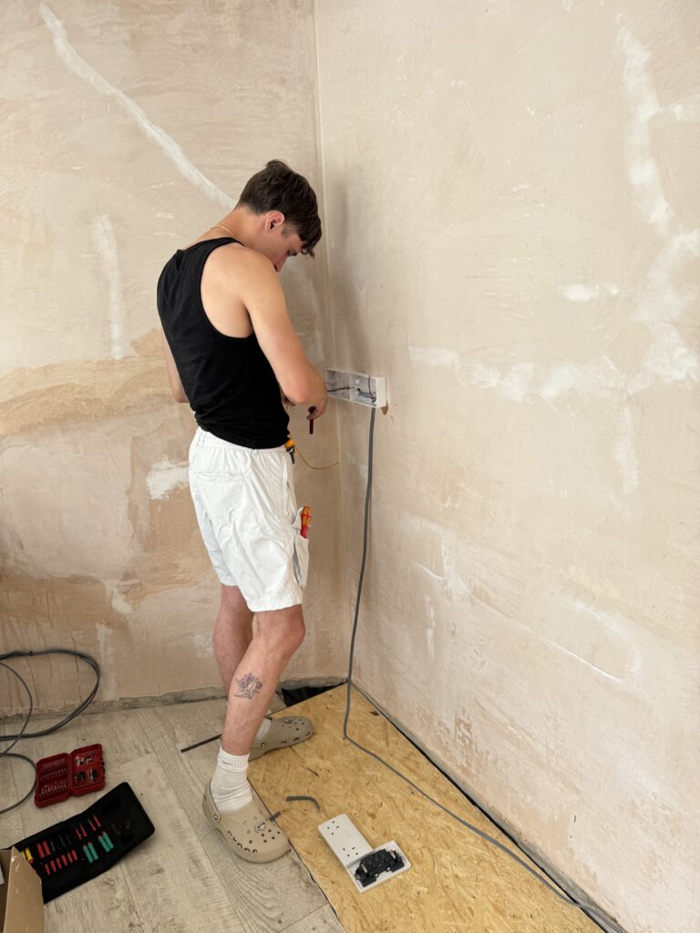
Before we began to drill holes I had to work out the placement of the sockets.
In the UK sockets in kitchens have to meet the following specifics to comply with regulations:
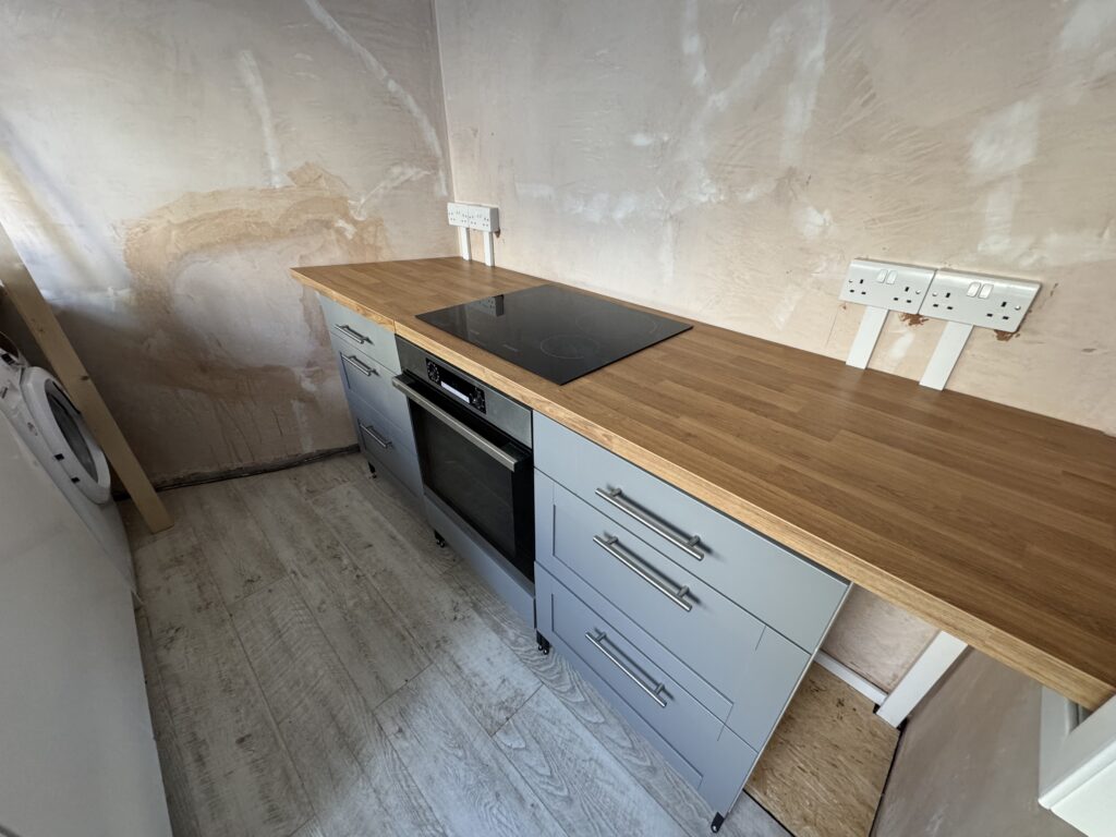
- Socket Placement Above Hobs: No socket outlets are permitted above any hob.
- Distance from Sinks & Hobs: Sockets must be a minimum of 300mm away from sinks and the edge of hobs.
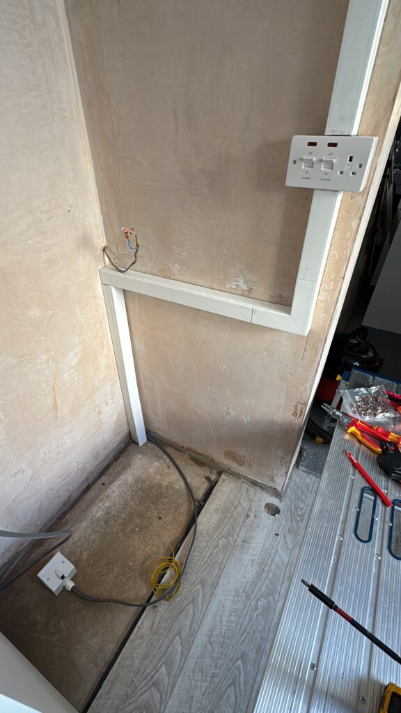
- Height Above Worktops: Sockets should be placed at least 150mm above the worktop surface to prevent water damage and allow for ease of use.
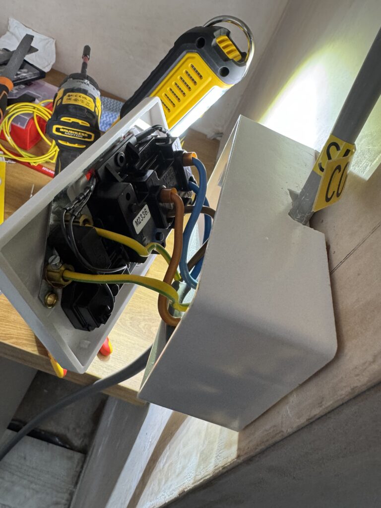
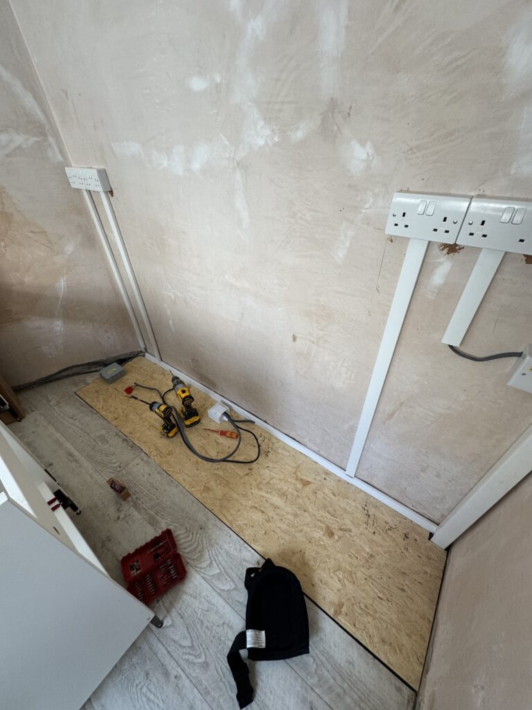
We fitted all of the socket back boxes to the walls ensuring that they were all at the same height (using my trusty laser level) and complied with the above.
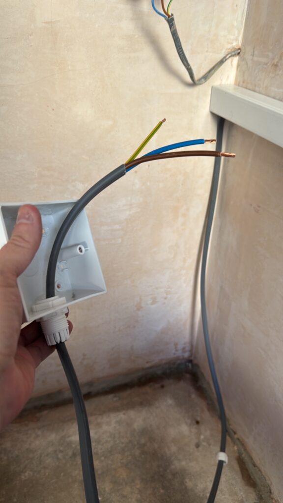
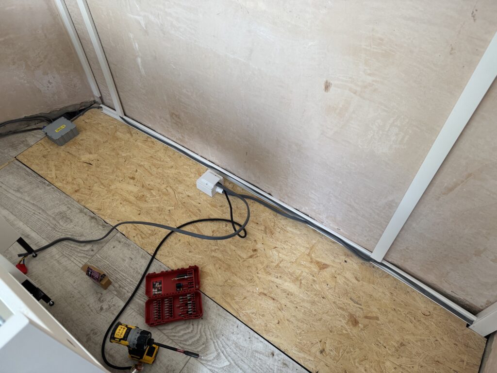
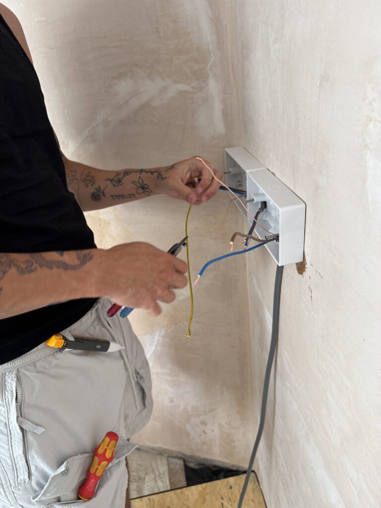
My son then set about dressing each socket and ensuring the cable runs were positioned perfectly to the containment (trunking) that I was busy measuring up and cutting (something that I am still a little better at doing than he is 😀 )
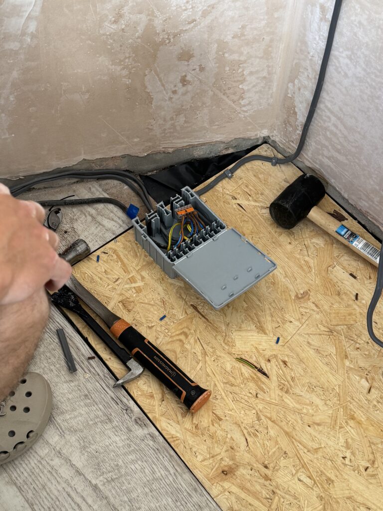
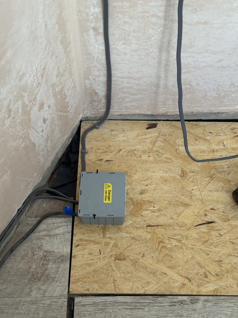
The boy finished off by joining the two halves of the ring into a Wago Box XL which would sit rather nicely under the drawer units and secured onto the OSB board.
With all that done I now had a working cooker and electrical system in the kitchen it was now onto:
- Install a new extractor fan for the hob
- Re-Install the cupboards
- Make and fit a number custom shelving units
- Sand and re-seal the existing sink counter top
- Cut, sand and fit counter up-stands & Fit a new Splash back for the hob
Which I will take you through in the next installments!